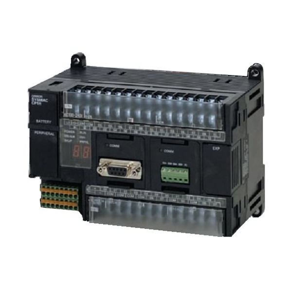
Servo Motor, PLC& HMI
| Models | CP1H-XA CPU Units | CP1H-X CPU Units | CP1H-Y CPU Units | |||
| CP1H-XA@@@–@ | CP1H-X@@@–@ | CP1H-Y@@@–@ | ||||
| Control method | Stored program method | |||||
| I/O control method | Cyclic scan with immediate refreshing | |||||
| Program language | Ladder diagram | |||||
| Function blocks | Maximum number of function block definitions: 128 Maximum number of instances: 256 Languages usable in function block definitions: Ladder diagrams, structured text (ST) | |||||
| Instruction length | 1 to 7 steps per instruction | |||||
| Instructions | Approx. 500 (function codes: 3 digits) | |||||
| Instruction execution time | Basic instructions: 0.10 ms min. Special instructions: 0.15 ms min. | |||||
| Common processing time | 0.7 ms | |||||
| Program capacity | 20K steps | |||||
| Number of tasks | 288 (32 cyclic tasks and 256 interrupt tasks) | |||||
| Maximum subroutine number | 256 | |||||
| Maximum jump number | 256 | |||||
| Work bits | 8,192 bits (512 words): W0.00 to W511.15 (W0 to W511)CIO Area: 37,504 bits (2,344 words): CIO 3800.00 to CIO 6143.15 (CIO 3800 to CIO 6143) | |||||
| TR Area | 16 bits: TR0 to TR15 | |||||
| Holding Area | 8,192 bits (512 words): H0.00 to H511.15 (H0 to H511) | |||||
| AR Area | Read-only (Write-prohibited): 7168 bits (448 words): A0.00 to A447.15 (A0 to A447) Read/Write: 8192 bits (512 words): A448.00 to A959.15 (A448 to A959) | |||||
| Timers | 4,096 bits: T0 to T4095 | |||||
| Counters | 4,096 bits: C0 to C4095 | |||||
| DM Area | 32 Kwords: D0 to D32767 | |||||
| Data Register Area | 16 registers (16 bits): DR0 to DR15 | |||||
| Index Register Area | 16 registers (32 bits): IR0 to IR15 | |||||
| Task Flag Area | 32 flags (32 bits): TK0000 to TK0031 | |||||
| Trace Memory | 4,000 words (500 samples for the trace data maximum of 31 bits and 6 words.) | |||||
| Memory Cassette | A special Memory Cassette (CP1W-ME05M) can be mounted. Note: Can be used for program backups and auto-booting. | |||||
| Clock function | Supported. Accuracy (monthly deviation): -4.5 min to -0.5 min (ambient temperature: 55°C),-2.0 min to +2.0 min (ambient temperature: 25°C), -2.5 min to +1.5 min (ambient temperature: 0°C) | |||||
| Memory backup | Flash memory: User programs, parameters (such as the PLC Setup), comment data, and the entire DM Area can be saved to flash memory as initial values.Battery backup: The Holding Area, DM Area, and counter values (flags, PV) are backed up by a battery. | |||||
| Battery service life | 5 years at 25°C. (Use the replacement battery within two years of manufacture.) | |||||
| Built-in input terminals | 40 (24 inputs, 16 outputs) | 20 (12 inputs, 8 outputs)Line-driver inputs: Two axes for phases A, B, and Z Line-driver outputs: Two axes for CW and CCW | ||||
| Number of connectable Expansion (I/O) Units | CP Expansion I/O Units: 7 max.; CJ-series Special I/O Units or CPU Bus Units: 2 max. | |||||
| Max. number of I/O points | 320 (40 built in + 40 per Expansion (I/O) Unit ´ 7 Units) | 300 (20 built in + 40 per Expansion (I/O) Unit ´ 7 Units) | ||||
| Interrupt inputs | 8 inputs (Shared by the external interrupt inputs (counter mode) and the quick-response inputs.) | 6 inputs (Shared by the external interrupt inputs (counter mode) and the quick-response inputs.) | ||||
| Interrupt input counter mode | 8 inputs (Response frequency: 5 kHz max. for all interrupt inputs), 16 bitsUp or down counters | 6 inputs (Response frequency: 5 kHz max. for all interrupt inputs), 16 bitsUp or down counters | ||||
| Quick-response inputs | 8 points (Min. input pulse width: 50 ms max.) | 6 points (Min. input pulse width: 50 ms max.) | ||||
| Scheduled interrupts | 1 | |||||
|
High-speed counters |
4 inputs: Differential phases (4x), 50 kHz or
Single-phase (pulse plus direction, up/down, increment), 100 kHz Value range: 32 bits, Linear mode or ring mode Interrupts: Target value comparison or range comparison |
2 inputs: Differential phases (4x), 500 kHz or Single-phase, 1 MHz and2 inputs: Differential phases (4x), 50 kHz or Single-phase (pulse plus direction, up/down, increment),100 kHz
Value range: 32 bits, Linear mode or ring mode Interrupts: Target value comparison or range comparison |
||||
| Built-in analog I/O terminals | 4 analog inputs and 2 analog outputs | None | ||||
| Analog control | 1 (Setting range: 0 to 255) | |||||
| External analog input | 1 input (Resolution: 1/256, Input range: 0 to 10 V), not isolated | |||||

