Servo Motor, PLC& HMI
| Item | Specifications |
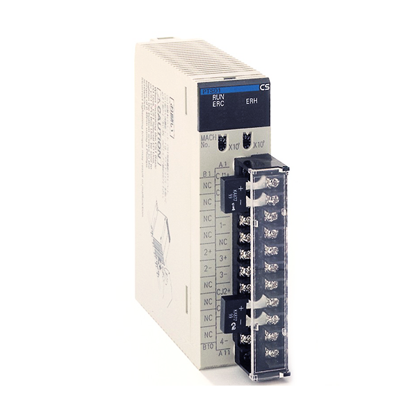
| Model | CS1W-PTS11 |
| Applicable PLC | CS Series |
| Unit type | CS-series Special I/O Unit |
| Mounting position | CS-series CPU Rack or CS-series Expansion Rack (Cannot be mounted to C200H Expansion I/O Rack or SYSMAC BUS Remote I/O Slave Rack.) |
| Maximum number of Units | 80 (within the allowable current consumption and power consumption range) |
| Unit numbers | 00 to 95 (Cannot duplicate Special I/O Unit numbers.) |
| Special I/O Unit Area | 10 words/Unit
Thermocouple Input Unit to CPU Unit: All process values, process value alarms (LL, L, H, HH), rate-of-change values, rate-of-change alarms (L, H), disconnection alarms, cold junction sensor errors |
|
DM Area words allocated to Special I/O Units |
100 words/Unit
CPU Unit to Thermocouple Input Unit: Temperature sensor type, input range (user set), scaling of process value data to be stored in allocated words in CIO area, rate-of-change input range, scaling of rate-of-change data, number of items for moving average, process value alarm setting (LL, L, H, HH), rate-of-change alarm setting (L, H), zero/span adjustment value, etc. |
|
Expansion Control/ Monitor Area |
35 words/Unit
CPU Unit to Thermocouple Input Unit: Designations and flags for beginning or resetting the hold function selection, adjustment period control, etc. Thermocouple Input Unit to CPU Unit: Adjustment period notices (with each input), peak and bottom values, top and valley values |
|
Expansion Setting Area |
46 words/Unit
CPU Unit to Thermocouple Input Unit: Expansion Control/Monitor Area settings, adjustment period control, peak and bottom detection, top and valley detection |
| Number of temperature sensor inputs | 4 |
| Temperature sensor types | The sensor type, input range, and scaling can be set individually for each of 4 inputs, which are each selectable from B, E, J, K, L, N, R, S, T, U, WRe5-26, PL II, and mV. |
| Scaling | Data to be stored in the allocated words in the CIO area must be scaled (individually for each of the 4 inputs, with the minimum and maximum values set). Data can be stored at 0% to 100%. |
|
Data storage in the CIO Area |
The value derived from carrying out the following processing in order of the actual process data in the input range is stored in four digits hexadecimal (binary values) in the allocated words in the CIO Area.
1) Mean value processing ® 2) Scaling ® 3) Zero/span adjustment ® 4) Output limits |
| Accuracy (25°C) | ±0.05% (Depends on the Sensor used and the measured temperature. Refer to Accuracy by Sensor Type and Measured Temperature Range on page 13 for details.) |
| Temperature coefficient | ±0.01% /°C (For full scale of electromotive force. See note.) |
| Resolution | 1/64,000 |
| Cold junction compensation error | ±1°C, at 20°C±10°C |
| Warmup time | 45 min |
| Maximum signal input | ±120 mV |
| Input impedance | 20 kΩ min. |
| Input disconnection detection current | 0.1 mA (typical) |
| Response time | 100 ms (travel time from input 0% to 90%, for ±100 mV step input and with moving average for 4 samples) |
| Conversion period | 20 ms/4 inputs, 10 ms/2 inputs. Can be switched in DM Area words allocated to the Unit as a Special I/O Unit. |
| Maximum time to store data in CPU Unit | Conversion period + one CPU Unit cycle |
|
Disconnection detection |
Detects disconnections at each input and turns ON the Disconnection Detection Flag. Hardware detection time: Approx. 0.5 s max.
The process value overrange direction for when a disconnection occurs can be specified. (High: 115% of set input range; low: -15% of set input range) |
| Mean value processing (input filter) | Calculates the moving average for the specified number of process values (1 to 128), and stores that value in the CIO Area as the process value. |
| Process value alarm | Process value 4-point alarm (HH, H, LL, L), alarm hysteresis, and ON-delay timer (0 to 60 s) are available. |
| Rate-of-change calculation | Calculates the amount of change per comparison time interval (1 to 16 s). |
| Rate-of-change alarm | Rate-of-change 2-point alarm (H, L), alarm hysteresis (shared with process value alarm), and ON-delay timer (0 to 60 s, shared with process value alarm) are available. |
| Adjustment period control | When zero/span adjustment is executed, the date is internally recorded at the Unit. When the preset zero/span adjustment period and number of days notice have elapsed, this function turns ON a warning flag to give notice that it is time for readjustment. |
| Peak and bottom detection | This function detects the maximum (peak) and minimum (bottom) analog input values, from when the Hold Start Bit (output) allocated to the Expansion Control/Monitor Area turns ON until it turns OFF, and stores them in the Expansion Control/Monitor Area. |
| Top and valley detection | This function detects the top and valley values for analog inputs, from when the Hold Start Bit (output) allocated to the Expansion Control/Monitor Area turns ON until it turns OFF, and stores them in the Expansion Control/Monitor Area. |
| Isolation | Between inputs and PLC signals, and between inputs: Isolation by transformer for power supply, and by photocoupler for signals. |
| Insulation resistance | 20 MΩ (at 500 V DC) between inputs |
| Dielectric strength | Between inputs: 1,000 V AC, at 50/60 Hz, for 1 min, leakage current 10 mA max. |

