Servo Motor, PLC& HMI
| Item | Specifications | ||||
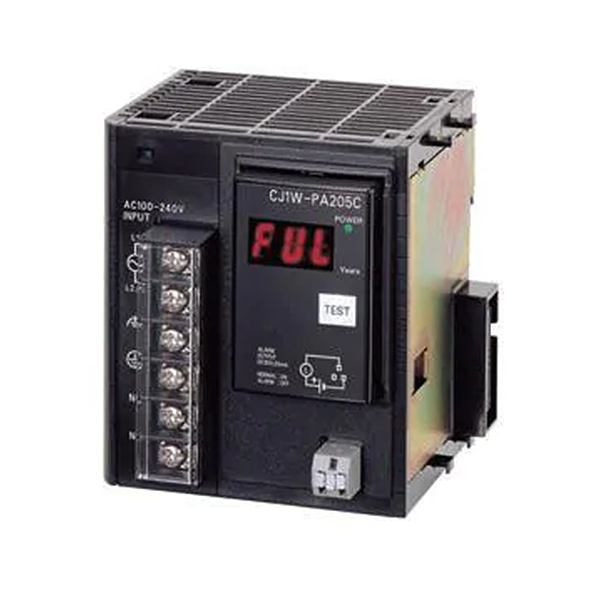
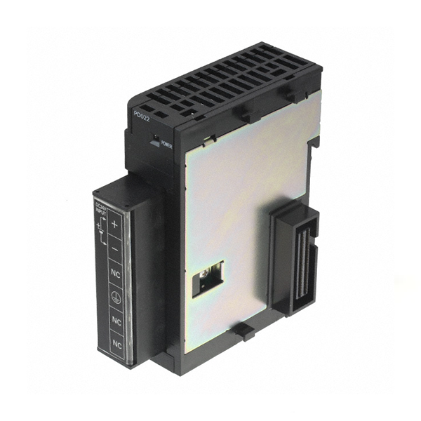
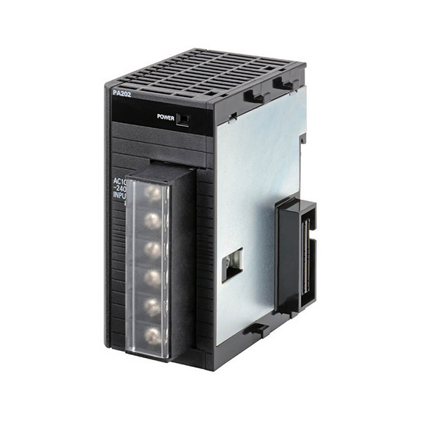
| Power Supply Unit | CJ1W-PA205R | CJ1W-PA205C | CJ1W-PA202 | CJ1W-PD025 | CJ1W-PD022 |
| Supply voltage | 100 to 240 V AC (wide-range), 50/60 Hz | 24 VDC | |||
| Operating voltage and frequency ranges | 85 to 264 V AC, 47 to 63 Hz | 19.2 to 28.8 V DC | 21.6 to 26.4 V DC | ||
| Power consumption | 100 VA max. | 50 VA max. | 50 W max. | 35 W max. | |
|
Inrush current (See note 1.) |
At 100 to 120 V AC:
15 A/8 ms max. for cold start at room temperature At 200 to 240 V AC: 30 A/8 ms max. for cold start at room temperature |
At 100 to 120 V AC:20 A/8 ms max. for cold start at room temperature At 200 to 240 V AC:
40 A/8 ms max. for cold start at room temperature |
At 24 V DC: 30 A/20 ms max. for cold start at room temperature |
||
| Output capacity (See note 7.) | 5.0 A, 5 V DC (including supply to CPU Unit) | 2.8 A, 5 V DC(including supply to CPU Unit) | 5.0 A, 5 V DC(including supply to CPU Unit) | 2.0 A, 5 V DC(including supply to CPU Unit) | |
| 0.8 A, 24 V DC | 0.4 A, 24 V DC | 0.8 A, 24 V DC | 0.4 A, 24 V DC | ||
| Total: 25 W max. | Total: 14 W max. | Total: 25 W max. | Total: 19.6 W max. | ||
| Output terminal (service supply) | Not provided. | ||||
| Replacement notifica- tion function | Not provided. | With Alarm output (open- collector output)30 V DC max., 50 mA max. | Not provided. | ||
|
Insulation resistance |
20 MΩ min. (at 500 V DC) between AC external and GR terminals (See note 3.) |
· 20 MΩ min. (at 500 V DC) between all external terminals and GR terminal (See note 3.), and between all alarm output terminals.· 20 MΩ 1 min. (at 250 V DC) between all alarm output terminals and GR terminal (See note 3.). |
20 MΩ min. (at 500 V DC) between AC external and GR terminals (See note 3.) |
20 MΩ min. (at 500 V DC) between DC external and GR terminals (See note 3.) |
— (See note 6.) |
|
Dielectric strength (See note 4.) |
2,300 V AC 50/60 Hz for 1 min between AC external and GR terminals (See note 3.) Leakage current: 10 mA max. |
· 2,300 VAC, 50/60 Hzfor 1 minute between all external terminals and GR terminal (See note 3.) and between all alarm output terminals with a leakage current of 10 mA max.
· 1,000 V AC, 50/60 Hz for 1 minute between all alarm output terminals and GR terminal (See note 3.) with a leakage current of 10 mA max. |
2,300 V AC 50/60 Hz for 1 min between AC external and GR terminals (See not 3.) Leakage current: 10 mA max. |
1,000 V AC, 50/60 Hz for 1 minute between DC external and GR terminals (See note 3.) Leakage current: 10 mA max. |
— (See note 6.) |
| 1,000 V AC, 50/60 Hz for 1 minute between DC external and GR terminals (See note 3.) Leakage current: 10 mA max. | |||||
| Noise immunity | 2 kV on power supply line (conforming to IEC61000-4-4) | ||||
| Vibration Resistance | Conforms to IEC60068-2-65 to 8.4 Hz with 3.5-mm amplitude, 8.4 to 150 Hz
Acceleration of 9.8 m/s2 for 100 min in X, Y, and Z directions (10 sweeps of 10 min each = 100 min total) |
||||
| Shock Resistance | Conforms to IEC60068-2-27147 m/s2, 3 times in X, Y, and Z directions (100 m/s2 for Relay Output Units) | ||||
| Ambient operating temperature | 0 to 55°C | ||||
| Ambient operating humidity | 10% to 90% (with no condensation) | 10% to 90% (with no condensation)(See note 5.) | 10% to 90% (with no condensation) | ||
| Atmosphere | Must be free from corrosive gases. | ||||
| Ambient storage temperature | -20 to 70°C (excluding battery) | -20 to 75°C (See note 5.) | -20 to 75°C (excluding battery) | ||
| Grounding | Less than 100 Ω | ||||
| Enclosure | Mounted in a panel. | ||||
| Weight | All models are each 5 kg max. | ||||

