Sensor
Features
| Dimensions (W x H x D) | 15.25 mm x 48.6 mm x 22.2 mm |
| Sensing distance | 11 mm |
| Sensing distance tolerance | ± 3 mm |
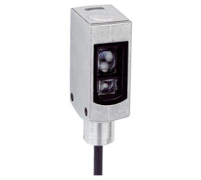
| Housing design (light emission) | Small, stainless steel |
| Light source | LED, RGB 1) |
| Wave length | 470 nm, 525 nm, 625 nm |
| Light emission | Long side of housing |
| Light spot size | 1.5 mm x 6.5 mm |
| Light spot direction | Vertical 2) |
| Receiving filters | None |
| Adjustment |
Cable, IO-Link Teach-in button |
| Teach-in mode | 2-point teach-in static/dynamic + proximity to mark |
- 1) Average service life: 100,000 h at TU = +25 °C.
- 2) In relation to long side of housing.
Mechanics/electronics
| Supply voltage | 12 V DC ... 24 V DC 1) |
| Ripple | ≤ 5 Vpp 2) |
| Current consumption | < 50 mA 3) |
| Switching frequency | 15 kHz 4) |
| Response time | 35 µs 5) |
| Jitter | 15 µs |
| Switching output | PNP |
| Switching output (voltage) | PNP: HIGH = UV ≤ 2 V / LOW approx. 0 V |
| Switching mode | Light/dark switching |
| Output current Imax. | 50 mA 6) |
| Retention time (ET) | 28 ms, non-volatile memory |
| Time delay | Switch-off delay, 520 ms (via IO-Link) |
| Connection type | Cable with M12 male connector, 4-pin, 0.2 m |
| Protection class | III |
| Circuit protection |
UV connections, reverse polarity protected Output Q short-circuit protected Interference pulse suppression |
| Enclosure rating | IP69K |
| Weight | 40 g |
| Housing material | Metal, ABS |
| Optics material | Plastic, PMMA |
| Indication |
LED indicator green: power on LED indicator, yellow: Status switching output Q |
- 1) Limit values: DC 12 V (–10 %) ... DC 24 V (+20 %). Operation in short-circuit protected network max. 8 A.
- 2) May not exceed or fall below Uv tolerances.
- 3) Without load.
- 4) With light/dark ratio 1:1.
- 5) Signal transit time with resistive load.
- 6) Total current of all Outputs.
Communication interface
|
|||||||||
| Process data structure A |
Bit 0 ... 2 = Emission Color Bit 3 … 12 = Measurment Value RGB Bit 13 … 15 = empty |
||||||||
| Process data structure B |
Bit 0 = switching signal QL1 Bit 1 … 10 = Measurment Value Emission Color Bit 11 ... 15 = empty |
||||||||
| Process data structure C |
Bit 0 = switching signal QL1 Bit 1 = Quality of Run Alarm Bit 2 = Teach successful Bit 3 = Teach busy Bit 4 ... 15 = empty |
||||||||
|
|||||||||
Ambient data
| Ambient operating temperature | –30 °C ... +70 °C |
| Ambient temperature, storage | –30 °C ... +75 °C |
| Shock load | According to IEC 60068 |
| UL File No. | NRKH.E348498 & NRKH7.E348498 |
Classifications
| ECl@ss 5.0 | 27270906 |
| ECl@ss 5.1.4 | 27270906 |
| ECl@ss 6.0 | 27270906 |
| ECl@ss 6.2 | 27270906 |
| ECl@ss 7.0 | 27270906 |
| ECl@ss 8.0 | 27270906 |
| ECl@ss 8.1 | 27270906 |
| ECl@ss 9.0 | 27270906 |
| ECl@ss 10.0 | 27270906 |
| ECl@ss 11.0 | 27270906 |
| ETIM 5.0 | EC001820 |
| ETIM 6.0 | EC001820 |
| ETIM 7.0 | EC001820 |
| ETIM 8.0 | EC001820 |
| UNSPSC 16.0901 | 39121528 |
Connection/pin assignment
| Connection type | Cable with M12 male connector, 4-pin, 0.2 m | ||||||||||
|
|||||||||||

